Our Products: USB High Speed - High Isolated - Industry Converter Interfaces
Highest quality - on the basis of our experience - we not accept compromise!
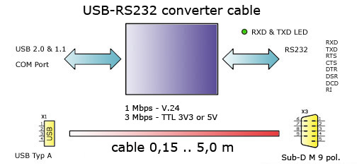
USB 2.0 <=> RS232 converter cable (product no. #230)
Available versions:
USB <=> RS232 v.24 converter cable (USB 2.0 & 1.1) Version 5.2
USB <=> RS232 TTL 5V converter cable (USB 2.0 & 1.1) Version 5.2
USB <=> RS232 TTL 3V3 converter cable (USB 2.0 & 1.1) Version 5.2
USB Modul:
USB Specification 2.0 & 1.1
Automatic "handshake mode"
Max. 1 Mbps "data transfer rate" V.24 version
Max. 3 Mbps "data transfer rate" TTL version
Aided "Remote wake-up" and power management
Plug & Play installing
Royal driver - FTDI Chipset
RS232 Receiver:
Latchup Free
ESD Protection for RS-232 I/O Pins:
±15kVHuman Body Model
±8kVIEC 1000-4-2, Contact Discharge
±15kVIEC 1000-4-2, Air-Gap Discharge
Guaranteed Data Rate 1 Mbps
Guaranteed Slew Rate 24V/µs
Meets EIA/TIA-232 Specifications Down to 3.0V
Ready-to-Transmit Logic-Level Output
Virtual COM port (VCP)
VCP drivers cause the USB device to appear as an additional
COM port available to the PC. Application software can access
the USB device in the same way as it would access a standard COM port.
Connection 1:
USB2.0 (1.1)
Pin assignment 1:
Pin 1 - USB Vcc
Pin 2 - USB Data-
Pin 3 - USB Data+
Pin 4 - USB GND
Connection 2:
RS232 - V.24 or TTL 3V3 or TTL 5V - SUB-D 9 pol. Male
Latchup Free
ESD Protection for RS-232 I/O Pins:
±15kVHuman Body Model
±8kVIEC 1000-4-2, Contact Discharge
±15kVIEC 1000-4-2, Air-Gap Discharge
Guaranteed Data Rate 1 Mbps
Guaranteed Slew Rate 24V/µs
Meets EIA/TIA-232 Specifications Down to 3.0V
Ready-to-Transmit Logic-Level Output
Handshake:
no
RTS / CTS
DSR / DTR
X-On / X-Off
Data transfer rates:
183, 300, 1200, 2400, 4800, 9600, 19200, 38400, 57600,
11520, 230400, 460800, 921600 bps.
TTL 3,3V and 5V up to 3000000 bps. Supported transfer rates PDF file
Status indication:
Red LED - TXD & RXD activity
Operating temperature:
-10..+70°C
Available Drivers:
Windows Vista, Windows Vista x64
Windows XP, Windows XP x64
Windows 2000
Windows Server 2008, Windows Server 2008 x64
Windows Server 2003, Windows Server 2003 x64
Windows 98, Windows ME
Mac OS X (Intel), Mac OS X, Mac OS 9, Mac OS 8
Linux, Linux x86_64
Windows CE 6.0, CE 4.2 - 5.2, Windows Mobile 6
Windows Mobile 5, PocketPC 2003
ARM/XScale Processor & x86 Processor
Windows CE 6.0 and CE 4.2 - 5.2
(Other Processors) - email support
Installing the USB-RS232 converter
The USB to RS232 converter is shipped with a Windows driver disk. When the converter is
connected to the Windows based host computer, Windows will display the
"Found New Hardware" screen and will prompt the user for a driver for the device.
With the driver disk installed in drive "A", select the "Have Disk" option and browse
the driver disk to the appropriate driver. Once installed, the USB converter will be
assigned the next available COM port on the host computer. To verify the proper set-up,
open the "System" icon in the "Control Panel" and click on the "Device Manager" tab.
Under "Ports", there should now be a new COM port labeled "USB Serial Port".
RS232 Info
In telecommunications, RS-232 (Recommended Standard 232) is a standard for serial binary
data signals connecting between a DTE (Data Terminal Equipment) and a DCE
(Data Circuit-terminating Equipment). It is commonly used in computer serial ports.
A similar ITU-T standard is V.24 .
Voltage levels
The RS-232 standard defines the voltage levels that correspond to logical one and
logical zero levels. Valid signals are plus or minus 3 to 15 volts. The range near
zero volts is not a valid RS-232 level; logic one is defined as a negative voltage,
the signal condition is called marking, and has the functional significance of OFF.
Logic zero is positive, the signal condition is spacing, and has the function ON.
The standard specifies a maximum open-circuit voltage of 25 volts; signal levels
of ±5 V,±10 V,±12 V, and ±15 V are all commonly seen depending on the power supplies
available within a device. RS-232 drivers and receivers must be able to withstand
indefinite short circuit to ground or to any voltage level up to ±25 volts.
Signals
Commonly-used signals are:
Transmitted Data (TxD)
Data sent from DTE to DCE.
Received Data (RxD)
Data sent from DCE to DTE.
Request To Send (RTS)
Asserted (set to logic 0, positive voltage) by DTE to prepare DCE to receive data.
This may require action on the part of the DCE, e.g. transmitting a carrier or
reversing the direction of a half-duplex channel. For the modern usage of
"RTS/CTS handshaking," see the section of that name.
Ready To Receive (RTR)
Asserted by DTE to indicate to DCE that DTE is ready to receive data. If in use,
this signal appears on the pin that would otherwise be used for Request To Send,
and the DCE assumes that RTS is always asserted; see RTS/CTS handshaking for details.
Clear To Send (CTS)
Asserted by DCE to acknowledge RTS and allow DTE to transmit. This signaling was
originally used with half-duplex modems and by slave terminals on multidrop lines:
The DTE would raise RTS to indicate that it had data to send, and the modem would
raise CTS to indicate that transmission was possible. For the modern usage of
"RTS/CTS handshaking," see the section of that name.
Data Terminal Ready (DTR)
Asserted by DTE to indicate that it is ready to be connected. If the DCE is a modem,
this may "wake up" the modem, bringing it out of a power saving mode. This behaviour
is seen quite often in modern PSTN and GSM modems. When this signal is de-asserted,
the modem may return to its standby mode, immediately hanging up any calls in progress.
Data Set Ready (DSR)
Asserted by DCE to indicate the DCE is powered on and is ready to receive commands
or data for transmission from the DTE. For example, if the DCE is a modem, DSR is
asserted as soon as the modem is ready to receive dialing or other commands;
DSR is not dependent on the connection to the remote DCE. If the DCE is not a modem
(e.g. a null modem cable or other equipment), this signal should be permanently asserted
(set to 0), possibly by a jumper to another signal.
Data Carrier Detect (DCD)
Asserted by DCE when a connection has been established with remote equipment.
Ring Indicator (RI)
Asserted by DCE when it detects a ring signal from the telephone line.
Maximum cable lengths
Cable length is one of the most discussed items in RS232 world. The standard has
a clear answer, the maximum cable length is 50 feet, or the cable length equal to
a capacitance of 2500 pF. The latter rule is often forgotten. This means that using
a cable with low capacitance allows you to span longer distances without going beyond
the limitations of the standard. If for example UTP CAT-5 cable is used with a typical
capacitance of 17 pF/ft, the maximum allowed cable length is 147 feet.
The cable length mentioned in the standard allows maximum communication speed to occur.
If speed is reduced by a factor 2 or 4, the maximum length increases dramatically.
Texas Instruments has done some practical experiments years ago at different baud rates
to test the maximum allowed cable lengths. Keep in mind, that the RS232 standard was
originally developed for 20 kbps. By halving the maximum communication speed, the allowed
cable length increases a factor ten!

)
)