Our Products: USB High Speed - High Isolated - Industry Converter Interfaces
Highest quality - on the basis of our experience - we not accept compromise!
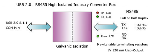
USB 2.0 - RS485 High Isolated Industry Converter Box - product #247
USB 2.0 <=> RS485 High Isolated Industry Converter Box (product no. #247)
Notes:
Extreme EMC-safe 8KV !
Extreme tough ! Designed for industry !
9 switchable terminating resistors !
Dimension outside boiler (mm) L 96 W 45 H 21 !
Low current consumption ! High-Speed Digital Isolator (no optocoupler) !
USB Modul:
USB Specification 2.0 & 1.1
Automatic switching Ready-Transmit
Max. 3 Mbps "data transfer rate"
Aided "Remote wake-up" and power management
Plug & Play installing
Royal driver - FTDI Chipset
RS485 Receiver:
+/- 15 kV Human Body Model
+/- 6 kV IEC 1000-4-2, Contact Discharge
+/- 12 kV IEC 1000-4-2, Air-Gap Discharge
Allow Up to 128 Receivers on the Bus
True-Fail-Safe Receiver
-7V .. +12V Common-Mode Range
Thermal Protection Against Output Short Circuit
RS485 Driver:
+/- 9 kV Human Body Model
Slev-Rate Limited for Errorless Data Transmission
-7V .. +12V Common-Mode Range
Current Limiting
Thermal Shutdown for Driver-Overload Protection
Galvanic Isolation:
High common-mode transient immunity: >25 kV/µs
Safety and regulatory approvals
UL recognition: 5000 V rms for 1 minute per UL 1577
CSA Component Acceptance Notice #5A
IEC 60950-1: 600 V rms (reinforced)
IEC 60601-1: 250 V rms (reinforced)
VDE certificate of conformity
DIN V VDE V 0884-10 (VDE V 0884-10):2006-12
VIORM = 846 V peak
EMC-safe: 8 KV
Excellent References:
Federal Armed Forces
Base stations of Cellular mobile telephony
Welding robots production line
With Ferrite - Shield Bead - 99,99 % reliability contra system crash
Extras:
Galvanically isolated +5V DC 120mA Output - Pin 9
Block diagram
Converter images
Technical characteristics
Product:
USB 2.0 <=> RS485 High Isolated Industry Converter Box
Virtual COM port (VCP)
VCP drivers cause the USB device to appear as an additional
COM port available to the PC. Application software can access
the USB device in the same way as it would access a standard COM port.
Connection 1:
USB2.0 (1.1)
Pin assignment 1:
Pin 1 - USB Vcc
Pin 2 - USB Data-
Pin 3 - USB Data+
Pin 4 - USB GND
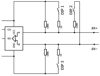
RX+/- Terminating resistor 100K
RX+ Pull Up resistor 100K
RX- Pull Down resistor 100K
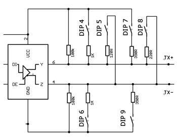
TX+/- Terminating resistor 100K
TX+ Pull Up resistor 100K
TX- Pull Down resistor 100K
Optional shiftable Terminating and Pull Up/Down resistors:
1 DIL - RX+ Pull Up resistor 1K
2 DIL - RX Terminating resistor 120R
3 DIL - RX- Pull Down resistor 1K
4 DIL - TX+ Pull Up resistor 1K
5 DIL - TX Terminating resistor 120R
6 DIL - TX- Pull Down resistor 1K
7 DIL - TX+ Pull Up resistor 390R
8 DIL - TX Terminating resistor 220R
9 DIL - TX- Pull Down resistro 390R
10 DIL - Local Echo_OFF
Halfduplex DIP 10 = ON / Fullduplex DIP 10 = OFF
Connection 2 guard:
RS485 Receiver:
+/- 15 kV Human Body Model
+/- 6 kV IEC 1000-4-2, Contact Discharge
+/- 12 kV IEC 1000-4-2, Air-Gap Discharge
Allow Up to 128 Receivers on the Bus
True-Fail-Safe Receiver
-7V .. +12V Common-Mode Range
Thermal Protection Against Output Short Circuit
RS485 Driver:
+/- 9 kV Human Body Model
Slev-Rate Limited for Errorless Data Transmission
-7V .. +12V Common-Mode Range
Current Limiting
Thermal Shutdown for Driver-Overload Protection
Handshake:
no
X-On / X-Off
TX/RX switching:
automatic
Transmission lines:
2-Wires Halfduplex or 4-Wires Fullduplex
Galvanic Isolation:
High common-mode transient immunity: >25 kV/µs
Safety and regulatory approvals
UL recognition: 5000 V rms for 1 minute per UL 1577
CSA Component Acceptance Notice #5A
IEC 60950-1: 600 V rms (reinforced)
IEC 60601-1: 250 V rms (reinforced)
VDE certificate of conformity
DIN V VDE V 0884-10 (VDE V 0884-10):2006-12
VIORM = 846 V peak
183, 300, 1200, 2400, 4800, 9600, 19200, 38400, 57600,
11520, 230400, 460800, 921600 bps.
TTL 3,3V and 5V up to 3000000 bps. Supported transfer rates PDF file
Status indication:
Red LED - TXD activity
Green LED - RXD activity
Green LED - +5V 120mA Output activity
Operating temperature:
-10..+70°C
Available Drivers:
Windows Vista, Windows Vista x64
Windows XP, Windows XP x64
Windows 2000
Windows Server 2008, Windows Server 2008 x64
Windows Server 2003, Windows Server 2003 x64
Windows 98, Windows ME
Mac OS X (Intel), Mac OS X, Mac OS 9, Mac OS 8
Linux, Linux x86_64
Windows CE 6.0, CE 4.2 - 5.2, Windows Mobile 6
Windows Mobile 5, PocketPC 2003
ARM/XScale Processor & x86 Processor
Windows CE 6.0 and CE 4.2 - 5.2
(Other Processors) - email support
Installing the USB-RS485 converter
The USB to RS485 converter is shipped with a Windows driver disk. When the converter is
connected to the Windows based host computer, Windows will display the
"Found New Hardware" screen and will prompt the user for a driver for the device.
With the driver disk installed in drive "A", select the "Have Disk" option and browse
the driver disk to the appropriate driver. Once installed, the USB converter will be
assigned the next available COM port on the host computer. To verify the proper set-up,
open the "System" icon in the "Control Panel" and click on the "Device Manager" tab.
Under "Ports", there should now be a new COM port labeled "USB Serial Port".
RS485 Info
EIA-485 only specifies electrical characteristics of the driver and the receiver. It does
not specify or recommend any data protocol. EIA-485 enables the configuration of inexpensive
local networks and multidrop communications links. It offers high data transmission speeds
(35 Mbit/s up to 10 m and 100 kbit/s at 1200 m). Since it uses a differential balanced line
over twisted pair (like EIA-422), it can span relatively large distances
(up to 4000 feet or just over 1200 metres).
In contrast to EIA-422, which has a single driver circuit which cannot be switched off,
EIA-485 drivers need to be put in transmit mode explicitly by asserting a signal to the
driver. This allows EIA-485 to implement linear topologies using only two wires. The
equipment located along a set of EIA-485 wires are interchangeably called nodes, stations
and devices.
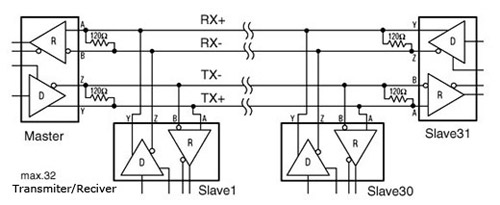
The recommended arrangement of the wires is as a connected series of point-to-point
(multidropped) nodes, a line or bus, not a star, ring, or multiply-connected network.
Ideally, the two ends of the cable will have a termination resistor connected across
the two wires. Without termination resistors, reflections of fast driver edges can
cause multiple data edges that can cause data corruption. Termination resistors also
reduce electrical noise sensitivity due to the lower impedance, and bias resistors are
required. The value of each termination resistor should be equal to the cable impedance
(typically, 120 ohms for twisted pairs).

)
)